지난 게시물에서 다양한 데이터 형식과 가능한 한 단순하게 유지하는 방법에 대해 간략하게 이야기했습니다. 이것이 첫 번째 프로젝트에 대한 마음으로 간단한 깜박이는 LED를 만들어 보겠습니다. 두 번째 Arduino에서 LED를 제어하는 하나의 Arduino가 있습니다. LED를 켜거나 끄는 컨트롤은 첫 번째 Arduino에서 두 번째 Arduino로 직렬을 통해 전송됩니다. 이것은 얻을만큼 기본입니다. 리모콘으로 아두이노 깜박임. LED에는 두 가지 상태만 있으므로 간단한 제어 코드를 사용할 수 있으며 시작하려면 켜짐 중 1을 사용하고 꺼짐에 0을 사용하고 있습니다.
이 예제에서는 Arduino Nanos를 사용하고 있지만 모든 종류의 Arduino를 사용할 수 있으며 이 시리즈에서는 Arduino와 Arduino 간의 통신을 사용하고 있습니다. 기술은 UART에서 UART로의 모든 장치에 대해 정확히 동일합니다. 예를 들어 Arduino에서 Bluetooth로 Arduino에서 Bluetooth를 통해 무선으로 정확히 동일한 직렬 통신 기술을 사용합니다.
Arduino 직렬 예제 #1: 원격 제어 깜박임 1
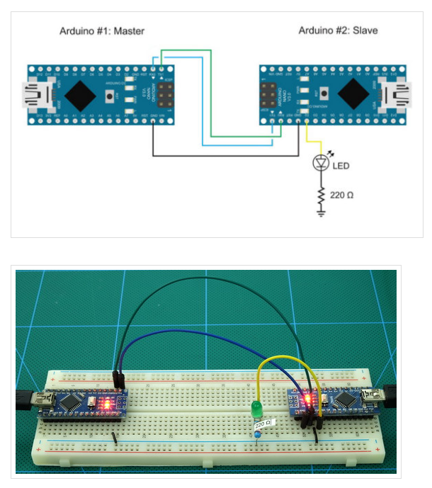
다음 연결을 사용하여 2개의 Arduino로 구성된 단순히 회로:
Arduino #1의 핀 0(RX)은 Arduino #2의 핀 1(TX)로 이동합니다.
Arduino #1의 핀 1(TX)은 Arduino #2의 핀 0(RX)으로 이동합니다.
Arduino #1 GND - Arduino #2 GND
Arduino #2 D2 - LED + 저항기(220 또는 330옴)
Arduino Serial Example #1 Remote Control Blink: Master
The master Arduino transmits the commands:
The slave Arduino receives the commands. If it receives a 1 it turns on the lED and if it receives a 0 it turns off the LED.
This is as simple as it gets.
Arduino #1 transmits a “1” waits a second then transmits a “0” then waits another second and starts again. It is worth mentioning that the master Arduino will happily keep transmitting the values whether or not there is anything listening.
Remember when you use Serial.print() numbers are converted to ascii. This means the actual values transmitted are 48 for 0 and 49 for 1. This is important to know for when you create the code for the slave Arduino.
The sketch on Arduino #2 initializes a hardware Serial channel, prints a “START” message to the serial monitor, and then keeps checking for incoming data. The loop() function is where the magic happens.
First a check is made to see if there is any data in the Serial buffer
If there is data in the buffer a single character is read and copied to the char variable called “c”. If you are not familiar with char and byte look up Arduino data types.
At this point we have a value in “c”. We are only interested is “0” and “1” so the next bit checks for these values.
If c==’0′ the LED is turned off with digitalWrite(LED, LOW); and if c==’1′ the LED is turned on with digitalWrite(LED, HIGH);. Any other value is ignored.
Notice that 0 and 1 are inside single quotes. This is because they are the ascii characters and I am using a char variable. With chars use single quotes ‘0’ and ‘1’ not double quotes such as “0” and “1”. Because I am using a char I could have also checked the actual value rather than the ascii character
This works in exactly the same way but is slightly harder to read.
Since we are only interested is “1”s and “0”s everything else is ignored. It is possible for the master device to send any character but the slave only acts on the “1”s and “0”s.
If you have already built the circuit you will need to remove the serial connections before uploading the sketches. If you forget to remove the serial connections the IDE will attempt to upload, fail and eventually timeout. Of course, after the upload you need to reconnect. This is one of the problems with using hardware serial and the disconnection / reconnection quickly gets annoying.
Upload the sketches and you should have Remote Blink. Remember it is the master Arduino that is controlling the LED.
You can also check the received data by opening th3e serial monitor on the slave Arduino.
Arduino Serial Example #2: Remote Control Blink 2
Using this technique it is fairly simply to add a second LED so let’s try it. Connect a second LED (plus resistor) to the Slave Arduino on pin D3.
Arduino Serial Example #2 Remote Control Blink: Master
I have added 2 more commands used to control the second LED:
“3” to turn on the LED, and
“2” to turn it off.
Arduino Serial Example #2 Remote Control Blink: Slave
The two new commands are taken care of with
You should be able to see that more LEDS can be added simply by using more commands.
Arduino Serial Example #3: Remote Control Blink 3
The above works well and is very reliable but if all you want to do is turn something on and off at regular intervals there is no need to use two Arduinos. So, next we make things a little more complex by adding a couple of switches to control the LEDs.
To the existing circuit, on Arduino #1 add a button switch on pin A0/D14 and A1/D15. If you don’t already know, analogue pins can be used as digital pins (except A5 & A6 which are analogue only). I only reason picked these pins is so the circuit diagram looked neat. No other reason.
I don’t spend much time on explaining the button switch code, if you are interested in learning more about this see the switching things on and off post.
Arduino Serial Example #3 Remote Control Blink: Master
The state of the button switches are checked and if the state has changed the control code is sent. The main bit is that the codes are only sent when the switch position changes.
Arduino Serial Example #3 Remote Control Blink: Slave
The slave skecth has not changed.
Now, instead of using a timer to send the commands button switches are used. Close a switch and an LED comes on. Open the switch and the LED turns off.
I find it a little annoying that the switches turn on the wrong LEDs but I will leave you to change it if you so wish.
Arduino Serial Example #4: Remote Control Blink Using Software Serial
If you followed along with the examples I suspect you were, at least a little, annoyed that you had to keep removing and reconnecting the wires to the serial pins. When writing this guide I forgot at least a couple of times. Although hardware serial is always the best choice if it is available to you it can be frustrating when developing the code. In the rest of the examples I will start using one of the software serial libraries. If you remember from part 1, the best option is AltSoftSerial followed by NeoSerial with the default SoftwareSerial at the end. In this example I change the example 3 from hardware serial to software serial using the software serial library that comes with the Arduino IDE. Not the best choice but useful is this scenario.
Technically you can use pins 0 and 1 for software serial but that would defeat what I am wanting to do, so, on the master Arduino I am using pins 2 and 3 (2 for TX and 3 for RX) and on the slave Arduino I am using pins 11 and 12 (11 for RX and 12 for TX).
Arduino Serial Example #4 Remote Control Blink Using Software Serial: Master
You should be able to see that I have removed the line that initialised the hardware serial and replaced it with
Where did “SoftSerial” come from? It is what I called the instance of the software serial I am using and this is done when you declare the library
I could have used any name (within reason), for example SWS or sSerial. When declaring the software serial library you need to specify what pins it is to use. Here I am telling it to use pin D2 for receive and D3 for transmit.
Arduino Serial Example #4 Remote Control Blink Using Software Serial: Slave
In the slave sketch, pins D2 and D3 are already used (bad planning I know) so I have used D11 and D12
If you give this a try you will find it works exactly the same as example 3 above. The difference is we do not need to remove the serial connections to upload a new sketch.
This has been a very gentle introduction in to using serial communication on the Arduino. Using single character codes or controls allows you to keep the code simple. A single character can be loaded in to a char or byte variable which is easy to compare or check, a simple ==. There is no need for char arrays or strings. If the character is not something we want it can be ignored and the next character read.
A key point to highlight is that the serial buffer is checked for data before attempting to read from it. This allows for non-blocking code that continues to work until there is data to process.
'Arduino' 카테고리의 다른 글
| Controlling a Solenoid Valve from an Arduino. Updated. (0) | 2022.03.13 |
|---|---|
| Arduino Serial Part 4: ASCII data and using markers to separate data (0) | 2022.03.13 |
| Arduino Serial Part 2: Serial Data (0) | 2022.03.13 |
| Arduino Serial Part 1 (0) | 2022.03.13 |
| [아두이노] 시리얼 통신 (0) | 2021.12.04 |