
소개
이 RS-485 센서 노드 모듈은
지능형 농업, 환경 모니터링, 홈 오토메이션 등과 같은
다양한 애플리케이션에 사용할 수 있는 사물 인터넷 장치입니다.
이 RS-485 센서 노드는
6채널 아날로그 입력과 1개의 SHT1x 온습도 디지털 입력을 제공합니다.
RS485 프로토콜은
각 노드 간 1200m 거리에서 최대 254개의 노드를 지원합니다.
이것은 환경 모니터링을 위한 광범위한 커버를 허용합니다.
RS-485 표준은 장거리 및 전기적으로 노이즈가 많은 환경에서 효과적으로 사용됩니다.
다중 데이타 수신기(센서 등)는 선형, 다중 드롭 구성으로 이러한 네트워크에 연결될 수 있습니다.
이러한 특성은 이를 산업 환경 및 유사한 애플리케이션에서 유용하게 만듭니다.
RS-485를 사용하면 저렴한 로컬 네트워크 및 멀티드롭 통신 링크를 구성할 수 있습니다.
데이터 전송 속도는 최대 10m에서 35Mbit/s, 1200m에서 100kbit/s입니다.
RS-485 버스는 업계에서 가장 널리 사용되는 통신 방식입니다.
RS-232 버스와 비교하여 더 낮은 비용으로 더 먼 거리의 정보를 전송할 수 있습니다.
RS-485를 세계적으로 널리 사용되는 이더넷과 통합하여
"사물 인터넷"을 구축하여 이 방법이 모든 장치를 저비용 고효율로 조정할 수 있기를 바랍니다.
응용범위
- 지능형 농업
- 공공 안전
- 환경 모니터링
- 개인의 건강
- 홈 오토메이션
사양
- MCU: Atmega8
- 입력 전압: 12V
- 전송 속도: 9600
- 슬레이브 주소: 0x01 - 0x7F
- RS-485 장거리, 안정적이고 안정적인 통신
- 다중 연결(최대 127개 모듈)
- 쉼고 빠른 케이블 연결
- 1개의 SHT1x 습도 및 온도 센서 인터페이스
- 6채널 아날로그 센서 인터페이스
- 슬레이브 주소를 직접 설정하기 위한 8개의 작은 스위치
- 습도: 0-100%RH(±4.5%RH)
- 온도:-40-128.8℃(±0.5℃)
- 크기: 82x50mm
핀아웃

자세한 내용은
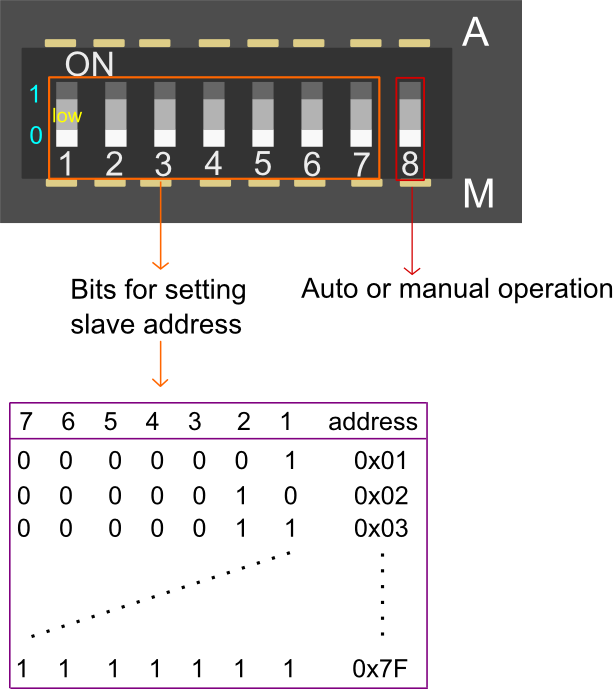
자동 또는 수동 작동: 이 비트는 소프트웨어 또는 하드웨어에 의해 슬레이브 장치의 주소를 설정하는 비트입니다.
- A: 소프트웨어를 통해 슬레이브 주소를 설정합니다. A 측에 있을 때 슬레이브 주소 설정용 비트는 무효가 됩니다.
- M: 하드웨어를 통해 슬레이브 주소를 설정합니다. M 쪽에 있을 때 7개의 작은 스위치를 통해 슬레이브 주소를 설정할 수 있음을 의미합니다. 30초 후에 설정에 성공합니다.
슬레이브 주소 설정용 비트: 0x01~0x7F, M 측에만 유효
제품 지침
- 모든 현재 실시간 데이터 지시문 확인--0x21
명령:
| Word Head | Device Addres | Frame Length | Command Word | Checksum |
| 0x55 | 0xAA | 0x11 | 0x00 | 0x21 |
이 명령은 현재 장치의 모든 데이터를 확인합니다.
레지스터 데이터는 총 10개입니다.
레지스터 데이터는 상위 8자리와 하위 8자리로 구성된 16자리입니다.
반환값
| Content Order | Register Illustration | Register Data | Register Range |
| 1 | 수동/자동으로 주소 상태 설정 | 0x00 0x01 | 자동의 경우 1; 수동의 경우 0 |
| 2 | 습도 측정 | 0x00 0x02 | 0.0 ~ 100.0%(RH) |
| 3 | 온도 측정 | 0x00 0x03 | -40.0 ~ 128.0(℃) |
| 4 | SHT1X 오류 상태 | 0x00 0x04 | 오류의 경우 1; 정상의 경우 0 |
| 5 | 아날로그 측정 1 | 0x00 0x05 | 0 ~ 1023 |
| 6 | 아날로그 측정 2 | 0x00 0x06 | 0 ~ 1023 |
| 7 | 아날로그 측정 3 | 0x00 0x07 | 0 ~ 1023 |
| 8 | 아날로그 측정 4 | 0x00 0x08 | 0 ~ 1023 |
| 9 | 아날로그 측정 5 | 0x00 0x09 | 0 ~ 1023 |
| 10 | 아날로그 측정 6 | 0x00 0x10 | 0 ~ 1023 |
명령어 설명: 내용 값은 2바이트로 구성됩니다. 0.0 ~ 100.0도는 0 ~ 1000을 의미합니다.
-40.0 ~ 128.0도는 -400 ~ 1280
반환 값:
| Word Head | Device Address | Frame Length | Command Word | Content | Checksum |
| 0x55 | 0xAA | 0x11 | 0x14 | 0x21 | H |
예 시 :
Send instruction:
| Word Head | Device Address | Frame Length | Command Word | Checksum |
| 0x55 | 0xAA | 0x11 | 0x00 | 0x21 |
Return instruction:
| 단어 머리 | 장치 주소 | 프레임 길이 | 명령어 | 콘텐츠1 | 콘텐츠2 | 콘텐츠3 |
| 0x55 | 0xAA | 0x11 | 0x14 | 0x21 | 0x00 0x00 | 0x00 0x00 |
| 콘텐츠4 | 콘텐츠5 | 콘텐츠6 | 콘텐츠7 | 콘텐츠8 | 콘텐츠9 | 콘텐츠10 |
| 0x00 0x01 | 0x00 0x66 | 0x00 0x99 | 0x00 0x66 | 0x00 0x99 | 0x00 0x66 | 0x00 0x99 |
- 모델 주소 설정 -- 0x55
명령:
| Word Head | Device Address | Frame Length | Command Word | Content | Checksum |
| 0x55 | 0xAA | 0xAB | 0x01 | 0x55 | 0x22 |
반환 값:
| 단어 머리 | 장치 주소 | 프레임 길이 | 명령어 | 콘텐츠 | 체크섬 |
| 0x55 | 0xAA | 0xAB | 0x01 | 0x55 | 0x22 |
명령어 설명:
0xAB는 브로드캐스트 주소, 즉 모든 모델의 공유 주소입니다.
불확실한 모델 상태에서 모델 주소를 설정하기 위해 주소 0xAB로 0x55를 보냅니다.
새 장치 주소에 따라 모델은 주소가 성공적으로 설정된 후 0x55를 반환합니다.
수동 상태에서 제품이 수동 및 자동으로 장치 주소를 설정할 수 있는 경우
0x55를 전송하면 현재 장치 주소를 설정할 수 없습니다.
그러면 반환 값은 수동 설정 주소 상태에서 제품을 나타내는 0xFE입니다.
반환 값:
| 단어 머리 | 장치 주소 | 프레임 길이 | 명령어 | 콘텐츠 | 체크섬 |
| 0x55 | 0xAA | 0xAB | 0x01 | 0x55 | 0xFF |
견본:
지시 보내기:
| 단어 머리 | 장치 주소 | 프레임 길이 | 명령어 | 콘텐츠 | 체크섬 |
| 0x55 | 0xAA | 0xAB | 0x01 | 0x55 | 0x11 |
이 샘플은 장치 주소를 0x11로 설정하는 데 사용됩니다.
주소를 수동으로 설정한 상태에서
지시 보내기:
| 단어 머리 | 장치 주소 | 프레임 길이 | 명령어 | 콘텐츠 | 체크섬 |
| 0x55 | 0xAA | 0xAB | 0x01 | 0x55 | 0x11 |
반환 지시:
| 단어 머리 | 장치 주소 | 프레임 길이 | 명령어 | 콘텐츠 | 체크섬 |
| 0x55 | 0xAA | 0xAB | 0x01 | 0x55 | 0xFF |
연결 다이어그램

샘플 코드
/*
# The Sample code for test the data of Analogue_Test and SHT1X Module

 # Editor : Lisper
 # Date   : 2013.12.9
 # Ver    : 1.3
 # Product: Analogue_Test and SHT1X Module
 # SKU    : DFR0233

 # Description:
 # Read the Analog value and the data of humidity & temperature

 # Hardwares:
 1. Arduino UNO
 2. IO Expansion Shield V5
 3. Analogue_Test and SHT1X Module

 # Interface: RS485
 # Note: Connect the Analogue_Test and SHT1X Module with IO Expansion Shield V5 through RS485
 Set the address of the module in manual,range from 0x02 to 0x7F,take effect after 30 seconds
*/

#define uint    unsigned  int
#define uchar   unsigned  char
#define ulong   unsigned  long
#define addr  0x02     //set address of the device for 0x02
uchar cmd[50];
uchar receive_ACK[100];
int EN = 2;

#if defined(ARDUINO) && ARDUINO >= 100
#include "Arduino.h"
#define printByte(args) Serial.write(args)
#define printlnByte(args)  Serial.write(args),Serial.println()
#else
#include "WProgram.h"
#define printByte(args) Serial.print(args,BYTE)
#define printlnByte(args)  Serial.println(args,BYTE)
#endif

void setup() {
  Serial.begin(9600);
  pinMode(2, OUTPUT); // TTL -> RS485 chip driver pin
}

void loop() {
  static ulong timepoint = 0;
  if (millis() - timepoint > 1000) {
    read_command();
    timepoint = millis();
  }
  if (Serial.available() > 0) data_return();

  //  delay(1000);

}

/************************Send command to Analogue_Test and SHT1X Module*************************/
void read_command()
{
  int i;
  char sum_cmd = 0;
  digitalWrite(EN, HIGH); // Turn the drvier pin to HIGH -> Turn on code transmitting mode for the RS485 interface
  // Turn the driver pin to LOW  -> Turn on reading mode for the RS485 interface
  delay(10);
  cmd[0] = 0x55;
  cmd[1] = 0xaa;
  cmd[2] = addr;
  cmd[3] = 0x00;
  cmd[4] = 0x21;
  for (i = 0; i < 5; i++) {
    sum_cmd += cmd[i];
  }
  cmd[5] = sum_cmd;

  for (i = 0; i < 6; i++) {

    printByte(cmd[i]);// command send to device
#if defined(ARDUINO) && ARDUINO >= 100
    Serial.flush();// complete the transmission of outgoing serial data
#endif
    delay(10);
  }
  digitalWrite(EN, LOW);
}
/************Feedback data of the Analog value and humidity & temperature ************/\


void data_return()
{
  digitalWrite(EN, LOW); // Turn the driver pin to LOW  -> Turn on reading mode for the RS485 interface
  delay(10);
  int i = 0;

  unsigned long timer = millis();

  while (true) {
    if (Serial.available()) {
      receive_ACK[i] = Serial.read();
      i++;
    }
    if (millis() - timer > 100) {
      break;
      Serial.println("Finish reading!");
    }
  }
  print_data () ;


  /*************************************************************************/
  // Display the original data

  //        for(int j = 0; j < 26; j++){
  //                Serial.print(receive_ACK[j],HEX); // return command
  //                Serial.print(" ");
  //        }
  //        Serial.println(" ");
}

void show_0x21_command(void)
{
  sht1x_data();
  Analog_test_data();

}

/************Deal with datas from Sht1x humidity & temperature sensor************/

void sht1x_data()
{
  uint humidity;
  uint temperature;
  humidity =  receive_ACK[7] * 256 + receive_ACK[8];
  temperature = receive_ACK[9] * 256 + receive_ACK[10];
  Serial.print("H:");
  Serial.print(humidity / 10, DEC);
  Serial.print("  ");
  Serial.print("T:");
  Serial.println(temperature / 10, DEC);
}

/********************Deal with datas from 6 Analog Sensors****************/
void Analog_test_data()
{
  char register_addr;
  uint  Analog_data;
  register_addr = 13;
  Serial.print("Analog Value:");
  for (int n = 1; n < 7; n++) {
    Analog_data = receive_ACK[register_addr] * 256 + receive_ACK[register_addr + 1];
    register_addr = register_addr + 2;
    Serial.print(Analog_data, DEC);
    Serial.print(" ");
  }
  Serial.println(" ");
  delay(1000);
}

/*************************** by lisper *********************************/
//print humidity and temperature
void print_data () {
  if (checksum ()) {        // if check sum is right
    Serial.println ();
    float humidity = read_uint8_t (receive_ACK, 7) / 10.0;
    Serial.print ("humidity=");
    Serial.println (humidity, 2);

    float temperature = (read_uint8_t (receive_ACK, 9) / 10.0);
    Serial.print ("temperature=");
    Serial.println (temperature, 2);
  }
  else {
    Serial.print ("\ncheck sum error! sum=");
    Serial.println (getsum_add (receive_ACK, 25), HEX);
  }
}

//if check sum is ok
boolean checksum () {
  uint8_t checksum = getsum_add (receive_ACK, 25);
  if (checksum == receive_ACK[25])
    return true;
  else
    return false;
}

//read 2 byte to uint16_t
uint16_t read_uint8_t (uint8_t *buffer, uint8_t sub) {        // Big-Endian, first byte is high byte
  return ((uint16_t)(buffer[sub]) << 8) + buffer[sub + 1];
}

//get check sum, add from 0 to length-1
uint8_t getsum_add (uint8_t *buffer, uint8_t length) {
  uint8_t sum;
  for (int i = sum = 0; i < length; i++) {
    sum += buffer[i];
  }
  return sum;
}
/*******************************************************************************/'MODBUS' 카테고리의 다른 글
| USB-DMX 인터페이스 어댑터/변환기(v1.0) (0) | 2022.02.24 |
|---|---|
| RS-485 및 Arduino – 빠른 입문서 (0) | 2022.02.24 |
| Modbus TCP/IP (0) | 2021.11.12 |
| 완전한 Modbus 가이드 (0) | 2021.09.06 |
| Arduino / ESP8266 / ESP32를 위한 저렴한 RS-485 인터페이스 (0) | 2021.09.02 |