Large Digit Driver Hookup GuideCONTRIBUTORS: SHAWN HYMEL
https://learn.sparkfun.com/tutorials/large-digit-driver-hookup-guide/all
Large Digit Driver Hookup Guide - SparkFun Learn
Introduction Large numerical displays are a great addition to any project where you want to be able to see information at a distance. Scorekeepers and lap timers would be a great application for large 7-segment LED displays. The Really Big 7-Segment Displa
learn.sparkfun.com
소개
큰 숫자 디스플레이는
멀리서 정보를 볼 수 있기를 원하는 모든 프로젝트에 큰 도움이 됩니다.
득점 기록원과 랩 타이머는
대형 7세그먼트 LED 디스플레이를 위한 훌륭한 애플리케이션이 될 것입니다.
여러 디스플레이를 동시에 구동하는 것이 편리할 것입니다.
여기에서 Large Digit Driver 보드 가 필요합니다.
 |
 |
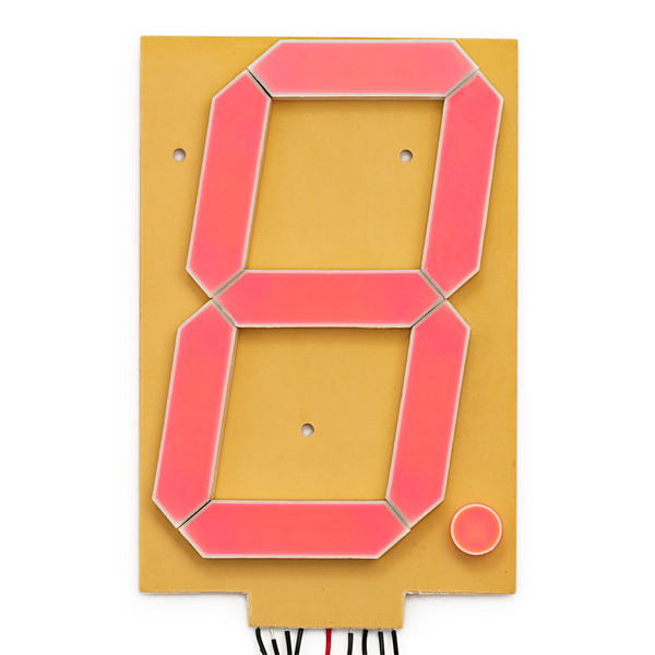
7-Segment Display - 6.5" (Red) SparkFun Large Digit Driver
Large Digit Driver는 7-Segment Display 하단에 직접 납땜할 수 있습니다.
여러 개의 큰 숫자 드라이버를 함께 연결하여 여러 숫자가 있는 디스플레이를 만들 수 있습니다
 |
 |
이 튜토리얼에서 다룹니다.
이 튜토리얼에서는 큰 숫자 드라이버에 대한 개요를 제공하고 드라이버를 Arduino에 연결하는 예를 제공합니다.
- 보드 개요 -- 먼저 브레이크아웃 보드의 각 핀과 그 기능을 살펴보겠습니다.
- 하드웨어 연결 -- 이 섹션에서는 큰 숫자 드라이버를 Arduino에 연결하는 방법을 보여줍니다.
- 예: 하나의 큰 숫자 -- 여기에서는 큰 숫자 드라이버를 통해 큰 7-세그먼트 디스플레이 중 하나를 제어하는 Arduino 스케치의 예를 제공합니다.
- 예: 두 개의 큰 숫자 -- 두 개의 큰 7-세그먼트 디스플레이를 함께 데이지 체인 방식으로 연결하고 두 개의 큰 숫자 드라이버로 제어하는 방법을 보여줍니다.
- 리소스 및 추가 정보 -- 이 섹션에서는 Large Digit Driver를 최대한 활용하기 위한 몇 가지 추가 리소스를 제공합니다.
사용 재료
이 튜토리얼을 따라 하려면 다음 자료가 필요합니다.
가지고 있는 것에 따라 모든 것이 필요하지 않을 수도 있습니다.
카트에 추가하고 가이드를 읽고 필요에 따라 카트를 조정하십시오.
이 자습서를 따라 하려면 몇 가지 구성 요소와 도구가 필요합니다.
다음은 하나의 7-세그먼트 디스플레이에 필요한 최소 부품입니다.
| 구 분 | 부품명 | 사진 |
| 1 | SparkFun 큰 숫자 드라이버 |  |
| 2 | 7-세그먼트 디스플레이 - 6.5"(빨간색) |  |
| 3 | 점퍼 와이어 프리미엄 6" M/F 팩 10개 | 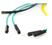 |
| 4 | SparkFun 레드보드 Qwiic |  |
| 5 | 벽면 어댑터 전원 공급 장치 - 12VDC, 600mA(배럴 잭) |
 |
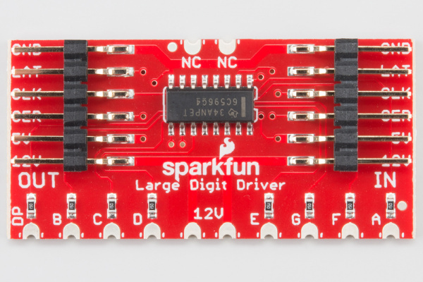
Board Overview
핀 설명
Large Digit Driver에는 6개의 입력 핀과 6개의 출력 핀이 있습니다.
 |
 |
 |
|
하드웨어 연결
보드 보호
Large Digit Driver를 7-세그먼트 디스플레이에 연결하기 전에
보드 뒷면에서 노출된 vias를 분리해야 합니다.
일부 드라이버 보드는 솔더 마스크로 덮이지 않은 스루홀 비아through-hole vias 로 생성됩니다.
결과적으로 7-세그먼트 디스플레이 뒷면의 트레이스 traces 가 단락될 수 있습니다.
드라이버 보드 뒷면의 비아를 덮기 위해 전기 테이프 나 고온 테이프 를 사용하는 것이 좋습니다 .

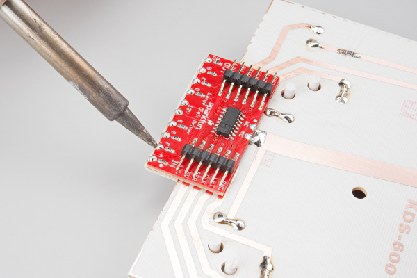
보드 부착
Large Digit Driver를 7-세그먼트 디스플레이 뒷면에 납땜해야 합니다.
드라이버의 10개 핀이 대형 7세그먼트 디스플레이의 하단을 향하도록 하고 7세그먼트 디스플레이 뒷면의 트레이스와 일렬로 정렬합니다. Soldering Castellated Vias Guide 에 따라 보드 상단에 있는 10개의 모든 성벽과 2개의 성벽을 납땜하십시오(12V 라인에 부착해야 하며 기계적 지원용임).
보드 연결
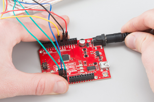
Arduino의 조정된 5V 및 조정되지 않은 12V(벽 어댑터에서)를 사용하여 7-세그먼트 디스플레이 및 대형 디지트 드라이버에 전원을 공급할 것입니다.
Large Digit Driver를 Arduino의 다음 핀에 연결합니다.
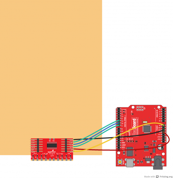
Large Digit Driver 아두이노
| GND | GND |
| LAT | 5 |
| CLK | 6 |
| SER | 7 |
| 5V | 5V |
| 12V | VIN |
예: 큰 숫자 하나
참고: 이 예에서는 데스크탑에서 최신 버전의 Arduino IDE를 사용하고 있다고 가정합니다.
Arduino를 처음 사용 하는 경우 Arduino IDE 설치에 대한 자습서를 검토하십시오.
한 자리 예제 코드 로드
USB 케이블을 통해 Arduino를 컴퓨터에 연결합니다. Arduino 프로그램을 열고 다음 스케치를 복사하십시오.
/*
 Controlling large 7-segment displays
 By: Nathan Seidle
 SparkFun Electronics
 Date: February 25th, 2015
 License: This code is public domain but you buy me a beer if you use this and we meet someday (Beerware license).

 The large 7 segment displays can be controlled easily with a TPIC6C594 IC. This code demonstrates how to control
 one display.

 Here's how to hook up the Arduino pins to the Large Digit Driver

 Arduino pin
 6 -> CLK (Green on the 6-pin cable)
 5 -> LAT (Blue)
 7 -> SER on the IN side (Yellow)
 5V -> 5V (Orange)
 Power Arduino with 12V and connect to Vin -> 12V (Red)
 GND -> GND (Black)

 There are two connectors on the Large Digit Driver. 'IN' is the input side that should be connected to
 your microcontroller (the Arduino). 'OUT' is the output side that should be connected to the 'IN' of addtional
 digits.

 Each display will use about 150mA with all segments and decimal point on.
*/

//GPIO declarations
//-=-=-=-=-=-=-=-=-=-=-=-=-=-=-=-=-=-=-=-=-=-=-=-=
byte segmentClock = 6;
byte segmentLatch = 5;
byte segmentData = 7;

//-=-=-=-=-=-=-=-=-=-=-=-=-=-=-=-=-=-=-=-=-=-=-=-=

void setup()
{
  Serial.begin(9600);
  Serial.println("Large Digit Driver Example");

  pinMode(segmentClock, OUTPUT);
  pinMode(segmentData, OUTPUT);
  pinMode(segmentLatch, OUTPUT);

  digitalWrite(segmentClock, LOW);
  digitalWrite(segmentData, LOW);
  digitalWrite(segmentLatch, LOW);

  int x = 0;
  while(1)
  {
    if(x == 9)
      postNumber(x, true); //Show decimal
    else
      postNumber(x, false);

    digitalWrite(segmentLatch, LOW);
    digitalWrite(segmentLatch, HIGH); //Register moves storage register on the rising edge of RCK
    delay(500);

    x++;
    x %= 10; //Reset x after 9

    Serial.println(x); //For debugging
  }
}

void loop()
{
  //showNumber(42); //Test pattern
}

//Takes a number and displays 2 numbers. Displays absolute value (no negatives)
void showNumber(float value)
{
  int number = abs(value); //Remove negative signs and any decimals

  //Serial.print("number: ");
  //Serial.println(number);

  for (byte x = 0 ; x < 2 ; x++)
  {
    int remainder = number % 10;

    postNumber(remainder, false);

    number /= 10;
  }

  //Latch the current segment data
  digitalWrite(segmentLatch, LOW);
  digitalWrite(segmentLatch, HIGH); //Register moves storage register on the rising edge of RCK
}

//Given a number, or '-', shifts it out to the display
void postNumber(byte number, boolean decimal)
{
  //    -  A
  //   / / F/B
  //    -  G
  //   / / E/C
  //    -. D/DP

#define a  1<<0
#define b  1<<6
#define c  1<<5
#define d  1<<4
#define e  1<<3
#define f  1<<1
#define g  1<<2
#define dp 1<<7

  byte segments;

  switch (number)
  {
    case 1: segments = b | c; break;
    case 2: segments = a | b | d | e | g; break;
    case 3: segments = a | b | c | d | g; break;
    case 4: segments = f | g | b | c; break;
    case 5: segments = a | f | g | c | d; break;
    case 6: segments = a | f | g | e | c | d; break;
    case 7: segments = a | b | c; break;
    case 8: segments = a | b | c | d | e | f | g; break;
    case 9: segments = a | b | c | d | f | g; break;
    case 0: segments = a | b | c | d | e | f; break;
    case ' ': segments = 0; break;
    case 'c': segments = g | e | d; break;
    case '-': segments = g; break;
  }

  if (decimal) segments |= dp;

  //Clock these bits out to the drivers
  for (byte x = 0 ; x < 8 ; x++)
  {
    digitalWrite(segmentClock, LOW);
    digitalWrite(segmentData, segments & 1 << (7 - x));
    digitalWrite(segmentClock, HIGH); //Data transfers to the register on the rising edge of SRCK
  }
}
운영
스케치를 Arduino에 업로드하고 12V 어댑터를 Arduino에 연결합니다.
7세그먼트 디스플레이를 뒤집습니다. 0-9(소수점은 9에 나타남)의 숫자를 세는 것을 볼 수 있습니다.

예: 두 개의 큰 숫자
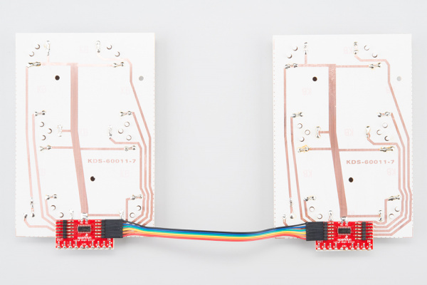
두 번째 숫자 첨부
6핀 점퍼 와이어를 사용하여 두 번째 7세그먼트 디스플레이를 첫 번째 디스플레이 장치에 연결합니다. 첫 번째 디스플레이에 있는 OUT의 GND를 두 번째 디스플레이에 있는 IN의 GND에 연결하고 첫 번째 디스플레이에 있는 OUT의 LAT를 두 번째 디스플레이에 있는 IN의 LAT에 연결하는 식으로 계속 연결해야 합니다.
두 자리 예제 코드 로드
Arduino가 USB 케이블을 사용하여 컴퓨터에 연결되어 있는지 확인하십시오.
다음 스케치를 Arduino 프로그램에 복사하십시오.
코드 복사    /*
 Controlling large 7-segment displays
 By: Nathan Seidle
 SparkFun Electronics
 Date: February 25th, 2015
 License: This code is public domain but you buy me a beer if you use this and we meet someday (Beerware license).

 This code demonstrates how to post two numbers to a 2-digit display usings two large digit driver boards.

 Here's how to hook up the Arduino pins to the Large Digit Driver IN

 Arduino pin 6 -> CLK (Green on the 6-pin cable)
 5 -> LAT (Blue)
 7 -> SER on the IN side (Yellow)
 5V -> 5V (Orange)
 Power Arduino with 12V and connect to Vin -> 12V (Red)
 GND -> GND (Black)

 There are two connectors on the Large Digit Driver. 'IN' is the input side that should be connected to
 your microcontroller (the Arduino). 'OUT' is the output side that should be connected to the 'IN' of addtional
 digits.

 Each display will use about 150mA with all segments and decimal point on.

*/

//GPIO declarations
//-=-=-=-=-=-=-=-=-=-=-=-=-=-=-=-=-=-=-=-=-=-=-=-=
byte segmentClock = 6;
byte segmentLatch = 5;
byte segmentData = 7;

//-=-=-=-=-=-=-=-=-=-=-=-=-=-=-=-=-=-=-=-=-=-=-=-=

void setup()
{
  Serial.begin(9600);
  Serial.println("Large Digit Driver Example");

  pinMode(segmentClock, OUTPUT);
  pinMode(segmentData, OUTPUT);
  pinMode(segmentLatch, OUTPUT);

  digitalWrite(segmentClock, LOW);
  digitalWrite(segmentData, LOW);
  digitalWrite(segmentLatch, LOW);
}

int number = 0;

void loop()
{
  showNumber(number); //Test pattern
  number++;
  number %= 100; //Reset x after 99

  Serial.println(number); //For debugging

  delay(500);
}

//Takes a number and displays 2 numbers. Displays absolute value (no negatives)
void showNumber(float value)
{
  int number = abs(value); //Remove negative signs and any decimals

  //Serial.print("number: ");
  //Serial.println(number);

  for (byte x = 0 ; x < 2 ; x++)
  {
    int remainder = number % 10;

    postNumber(remainder, false);

    number /= 10;
  }

  //Latch the current segment data
  digitalWrite(segmentLatch, LOW);
  digitalWrite(segmentLatch, HIGH); //Register moves storage register on the rising edge of RCK
}

//Given a number, or '-', shifts it out to the display
void postNumber(byte number, boolean decimal)
{
  //    -  A
  //   / / F/B
  //    -  G
  //   / / E/C
  //    -. D/DP

#define a  1<<0
#define b  1<<6
#define c  1<<5
#define d  1<<4
#define e  1<<3
#define f  1<<1
#define g  1<<2
#define dp 1<<7

  byte segments;

  switch (number)
  {
    case 1: segments = b | c; break;
    case 2: segments = a | b | d | e | g; break;
    case 3: segments = a | b | c | d | g; break;
    case 4: segments = f | g | b | c; break;
    case 5: segments = a | f | g | c | d; break;
    case 6: segments = a | f | g | e | c | d; break;
    case 7: segments = a | b | c; break;
    case 8: segments = a | b | c | d | e | f | g; break;
    case 9: segments = a | b | c | d | f | g; break;
    case 0: segments = a | b | c | d | e | f; break;
    case ' ': segments = 0; break;
    case 'c': segments = g | e | d; break;
    case '-': segments = g; break;
  }

  if (decimal) segments |= dp;

  //Clock these bits out to the drivers
  for (byte x = 0 ; x < 8 ; x++)
  {
    digitalWrite(segmentClock, LOW);
    digitalWrite(segmentData, segments & 1 << (7 - x));
    digitalWrite(segmentClock, HIGH); //Data transfers to the register on the rising edge of SRCK
  }
}
운영
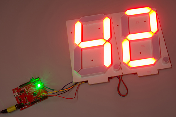
스케치를 Arduino에 업로드하고 12V 전원을 연결하십시오. 7-세그먼트 디스플레이(이제 2자리!)는 00에서 99까지 세어야 합니다.
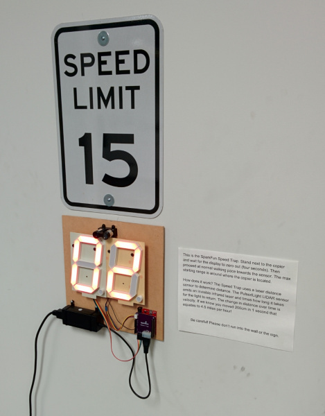
예: 스피드 트랩
디스플레이를 보여주기 위해 우리는 벽에서 사람까지의 거리를 측정하는 장치를 만들었습니다. 거리가 변하면 속도를 계산할 수 있습니다. SparkFun Speed Trap을 소개합니다!
필요한 부품 목록은 다음과 같습니다.